- 1. DEP 3273 : COMMUNICATION
SYSTEM FUNDAMENTALS
1
- 2. COURSE LEARNING OUTCOME
Upon completion of this course, students should be able to:-
1. apply the basic concept of communication system elements,
various types of modulation techniques, transmission system
and basic data communication in electronic communication by
using appropriate diagram. (C3, PLO1)
2. solve a well-defined problems related to noise parameters,
modulation parameters, character encoding and information
capacity using designated method and formula. (C3, PLO2)
3. construct and test various applications of related
communication equipments in performing the assigned
practical work using standard test equipment. (P4, PLO5)
4. demonstrate ability to work in a team to complete assigned
tasks during practical work sessions. (A3, PLO11)
2
- 3. CHAPTER 1
INTRODUCTION TO COMMUNICATION SYSTEM
(06 : 00)
LEARNING OUTCOME
1.1 Know the element in basic communication system.
1.2 Know noise, interference and distortion.
1.3 Know Signal-to-Noise Power Ratio, Noise Factor and Noise
Figure.
1.4 Apply SNR, Noise Factor, and Noise Figure formula.
1.5 Know the frequency spectrum, bandwidth, and wavelength.
1.6 Apply bandwidth and wavelength formula.
1.7 Understand Transmission Modes.
1.8 Understand various types of communication system.
3
- 4. 1.1 Know the element in basic communication
system
At the end of this learning session, student
should be able to explain :
- Definition Communication System
- The elements in communication system
- Block diagram of communication system.
4
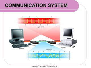
- 5. COMMUNICATION SYSTEM
Hanisah/EP301/JKE/POLISAS/Dis 12
5
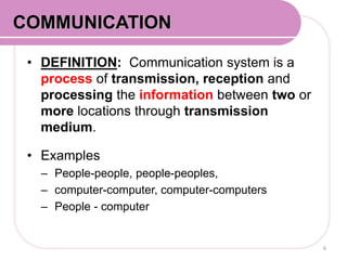
- 6. • DEFINITION: Communication system is a
process of transmission, reception and
processing the information between two or
more locations through transmission
medium.
• Examples
– People-people, people-peoples,
– computer-computer, computer-computers
– People - computer
6
COMMUNICATION
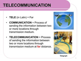
- 7. • TELE (in Latin) = Far
• COMMUNICATION = Process of
sending the information between two
or more locations through
transmission medium.
• TELECOMMUNICATION = Process
of sending the information between
two or more locations through
transmission medium at far distance.
7
COMMUNICATION SYSTEMTELECOMMUNICATION
Telegraph
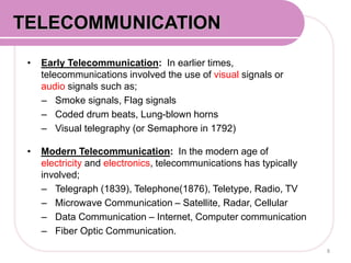
- 8. • Early Telecommunication: In earlier times,
telecommunications involved the use of visual signals or
audio signals such as;
– Smoke signals, Flag signals
– Coded drum beats, Lung-blown horns
– Visual telegraphy (or Semaphore in 1792)
• Modern Telecommunication: In the modern age of
electricity and electronics, telecommunications has typically
involved;
– Telegraph (1839), Telephone(1876), Teletype, Radio, TV
– Microwave Communication – Satellite, Radar, Cellular
– Data Communication – Internet, Computer communication
– Fiber Optic Communication.
8
COMMUNICATION SYSTEMTELECOMMUNICATION
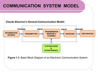
- 9. COMMUNICATION SYSTEM MODEL
INFORMATION
SOURCE
TRANSMITTER
TRANSMISSION
MEDIUM or
CHANNEL
RECEIVER DESTINATION
SYSTEM NOISE
&
INTERFERENCE
message messagesignal signal
Claude Shannon’s General Communication Model;
Figure 1.1: Basic Block Diagram of an Electronic Communication System
9
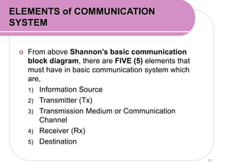
- 10. From above Shannon’s basic communication
block diagram, there are FIVE (5) elements that
must have in basic communication system which
are,
1) Information Source
2) Transmitter (Tx)
3) Transmission Medium or Communication
Channel
4) Receiver (Rx)
5) Destination
ELEMENTS of COMMUNICATION
SYSTEM
10
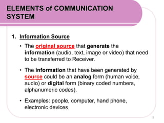
- 11. 1. Information Source
• The original source that generate the
information (audio, text, image or video) that need
to be transferred to Receiver.
• The information that have been generated by
source could be an analog form (human voice,
audio) or digital form (binary coded numbers,
alphanumeric codes).
• Examples: people, computer, hand phone,
electronic devices
11
ELEMENTS of COMMUNICATION
SYSTEM
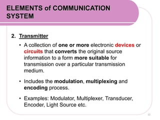
- 12. 2. Transmitter
• A collection of one or more electronic devices or
circuits that converts the original source
information to a form more suitable for
transmission over a particular transmission
medium.
• Includes the modulation, multiplexing and
encoding process.
• Examples: Modulator, Multiplexer, Transducer,
Encoder, Light Source etc.
12
ELEMENTS of COMMUNICATION
SYSTEM
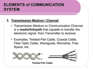
- 13. 3. Transmission Medium / Channel
• Transmission Medium or Communication Channel
is a media/link/path that capable to transfer the
electronic signal from Transmitter to receiver.
• Examples: Twisted Pair Cable, Coaxial Cable,
Fiber Optic Cable, Waveguide, Microstrip, Free
Space, etc.
13
ELEMENTS of COMMUNICATION
SYSTEM
Twisted Pair Cable
- 14. 14
ELEMENTS of COMMUNICATION
SYSTEM
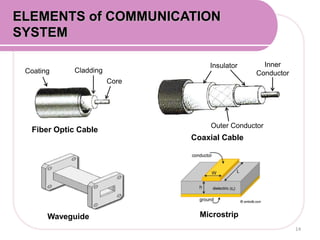
Fiber Optic Cable
Coaxial Cable
Core
CladdingCoating
Inner Conductor
Inner
Conductor
Outer Conductor
Insulator
Waveguide Microstrip
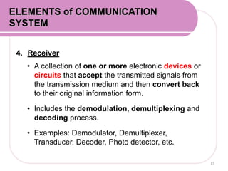
- 15. 4. Receiver
• A collection of one or more electronic devices or
circuits that accept the transmitted signals from
the transmission medium and then convert back
to their original information form.
• Includes the demodulation, demultiplexing and
decoding process.
• Examples: Demodulator, Demultiplexer,
Transducer, Decoder, Photo detector, etc.
15
ELEMENTS of COMMUNICATION
SYSTEM
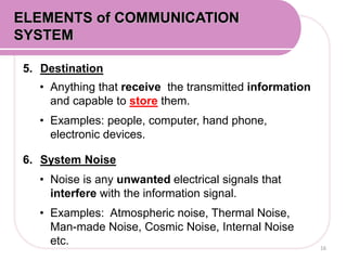
- 16. 5. Destination
• Anything that receive the transmitted information
and capable to store them.
• Examples: people, computer, hand phone,
electronic devices.
6. System Noise
• Noise is any unwanted electrical signals that
interfere with the information signal.
• Examples: Atmospheric noise, Thermal Noise,
Man-made Noise, Cosmic Noise, Internal Noise
etc. 16
ELEMENTS of COMMUNICATION
SYSTEM
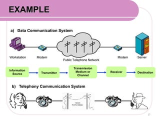
- 17. a) Data Communication System
EXAMPLE
Information
Source
b) Telephony Communication System
Transmitter
Transmission
Medium or
Channel
Receiver Destination
17
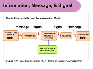
- 18. INFORMATION
SOURCE
TRANSMITTER
TRANSMISSION
MEDIUM or
CHANNEL
RECEIVER
DESTINATION
SYSTEM NOISE &
INTERFERENCE
message messagesignal signal
Claude Shannon’s General Communication Model;
Figure 1.1: Basic Block Diagram of an Electronic Communication System
18
Information, Message, & Signal
info info
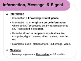
- 19. Information
• Information = knowledge = intelligence.
• Information is an original source information
which do NOT processed yet by transmitter or do
NOT converted into signal.
• It can be stored in people or any devices like
computer, digital camera, video camera, recorder
etc.
• Examples: audio, alphanumeric, text, image, video.
Message
• Message represents the content of Information.
19
Information, Message, & Signal
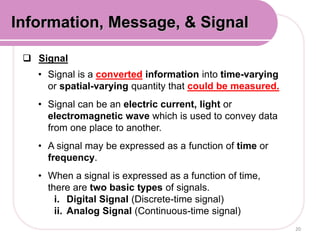
- 20. Signal
• Signal is a converted information into time-varying
or spatial-varying quantity that could be measured.
• Signal can be an electric current, light or
electromagnetic wave which is used to convey data
from one place to another.
• A signal may be expressed as a function of time or
frequency.
• When a signal is expressed as a function of time,
there are two basic types of signals.
i. Digital Signal (Discrete-time signal)
ii. Analog Signal (Continuous-time signal)
20
Information, Message, & Signal
- 21. 21
Information, Message, & Signal
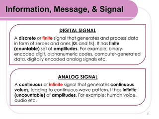
DIGITAL SIGNAL
A discrete or finite signal that generates and process data
in form of zeroes and ones (0s and 1s). It has finite
(countable) set of amplitudes. For example; binary-
encoded digit, alphanumeric codes, computer-generated
data, digitally encoded analog signals etc.
ANALOG SIGNAL
A continuous or infinite signal that generates continuous
values, leading to continuous wave pattern. It has infinite
(uncountable) of amplitudes. For example; human voice,
audio etc.
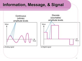
- 22. 22
Information, Message, & Signal
Continuous
(infinite)
amplitude levels
Discrete
(countable)
amplitude levels
- 23. 1.2 Know noise, interference and distortion
1.3 Know Signal-to-Noise Power Ratio, Noise Factor and
Noise Figure
1.4 Apply SNR, Noise Factor, and Noise Figure formula
At the end of this learning session, student should be able
to explain and apply :
- Internal and External Noise
- Interference
- Distortion
- Signal-to-Noise Power Ratio (SNR)
- Noise Factor (F) and Noise Figure (NF)
23
- 24. NOISE, DISTORTION &
INTERFERENCE
24
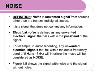
- 25. • DEFINITION: Noise is unwanted signal from sources
other than the transmitted signal source.
• It is a signal that does not convey any information.
• Electrical noise is defined as any unwanted
electrical signal that falls within the passband of the
signal.
• For example, in audio recording, any unwanted
electrical signals that fall within the audio frequency
band of 0 Hz to 15kHz will interfere the music will be
considered as NOISE.
• Figure 1.5 shows the signal with noise and the signal
without noise.
25
NOISE
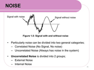
- 26. • Particularly noise can be divided into two general categories;
– Correlated Noise (No Signal, No noise)
– Uncorrelated Noise (Always has noise in the system)
• Uncorrelated Noise is divided into 2 groups;
– External Noise
– Internal Noise
26
NOISE
Figure 1.5: Signal with and without noise
Signal with noise Signal without noise
- 27. • DEFINITION: External Noise is the noise
which is generated outside the device or
circuit system.
• External noises are somewhat
uncontrollable and these are:
1. Atmospheric Noise
2. Extra-Terrestrial/ Space Noise
3. Man-made or Industrial Noise
27
EXTERNAL NOISE
Hanisah/EP301/JKE/POLISAS/Dis12
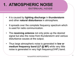
- 28. • It is caused by lighting discharge in thunderstorm
and other natural disturbance in atmosphere.
• It spreads over the complete frequency spectrum which
is used for radio communication.
• The receiving antenna not only picks up the desired
signal but also the noise from thunderstorm and various
disturbance causes at the output.
• Thus large atmospheric noise is generated in low or
medium frequency band (LF @ MF) while very little
noise is generated in very high frequency(VHF) band.
28
1. ATMOSPHERIC NOISE
EXTERNAL NOISE
Hanisah/EP301/JKE/POLISAS/Dis12
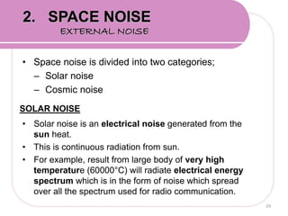
- 29. • Space noise is divided into two categories;
– Solar noise
– Cosmic noise
SOLAR NOISE
• Solar noise is an electrical noise generated from the
sun heat.
• This is continuous radiation from sun.
• For example, result from large body of very high
temperature (60000°C) will radiate electrical energy
spectrum which is in the form of noise which spread
over all the spectrum used for radio communication.
29
2. SPACE NOISE
EXTERNAL NOISE
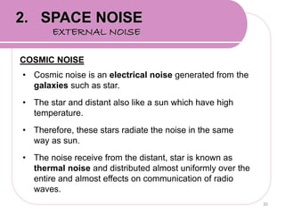
- 30. COSMIC NOISE
• Cosmic noise is an electrical noise generated from the
galaxies such as star.
• The star and distant also like a sun which have high
temperature.
• Therefore, these stars radiate the noise in the same
way as sun.
• The noise receive from the distant, star is known as
thermal noise and distributed almost uniformly over the
entire and almost effects on communication of radio
waves.
30
2. SPACE NOISE
EXTERNAL NOISE
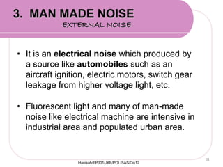
- 31. • It is an electrical noise which produced by
a source like automobiles such as an
aircraft ignition, electric motors, switch gear
leakage from higher voltage light, etc.
• Fluorescent light and many of man-made
noise like electrical machine are intensive in
industrial area and populated urban area.
31
3. MAN MADE NOISE
EXTERNAL NOISE
Hanisah/EP301/JKE/POLISAS/Dis12
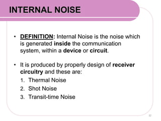
- 32. • DEFINITION: Internal Noise is the noise which
is generated inside the communication
system, within a device or circuit.
• It is produced by properly design of receiver
circuitry and these are:
1. Thermal Noise
2. Shot Noise
3. Transit-time Noise
32
INTERNAL NOISE
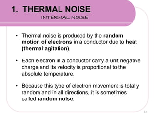
- 33. • Thermal noise is produced by the random
motion of electrons in a conductor due to heat
(thermal agitation).
• Each electron in a conductor carry a unit negative
charge and its velocity is proportional to the
absolute temperature.
• Because this type of electron movement is totally
random and in all directions, it is sometimes
called random noise.
33
1. THERMAL NOISE
INTERNAL NOISE
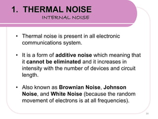
- 34. • Thermal noise is present in all electronic
communications system.
• It is a form of additive noise which meaning that
it cannot be eliminated and it increases in
intensity with the number of devices and circuit
length.
• Also known as Brownian Noise, Johnson
Noise, and White Noise (because the random
movement of electrons is at all frequencies).
34
1. THERMAL NOISE
INTERNAL NOISE
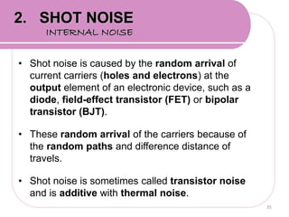
- 35. • Shot noise is caused by the random arrival of
current carriers (holes and electrons) at the
output element of an electronic device, such as a
diode, field-effect transistor (FET) or bipolar
transistor (BJT).
• These random arrival of the carriers because of
the random paths and difference distance of
travels.
• Shot noise is sometimes called transistor noise
and is additive with thermal noise.
35
2. SHOT NOISE
INTERNAL NOISE
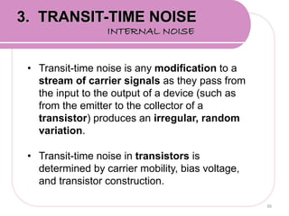
- 36. • Transit-time noise is any modification to a
stream of carrier signals as they pass from
the input to the output of a device (such as
from the emitter to the collector of a
transistor) produces an irregular, random
variation.
• Transit-time noise in transistors is
determined by carrier mobility, bias voltage,
and transistor construction.
36
3. TRANSIT-TIME NOISE
INTERNAL NOISE
- 37. • DEFINITION: Distortion is any changes in the
original signal which has a corrupting effect on its
form or shape.
• It is the modification of the original shape (or other
characteristics) of original information signal.
• It creates unwanted frequencies (Harmonics) that
interfere with the original signal and degrade the
performance.
• It is a kind of Correlated noise which the
noise(distortion) is exist when the signal is exist.
37
DISTORTION
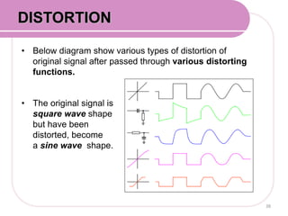
- 38. • Below diagram show various types of distortion of
original signal after passed through various distorting
functions.
• The original signal is
square wave shape
but have been
distorted, become
a sine wave shape.
38
DISTORTION
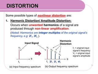
- 39. Some possible types of nonlinear distortion are:
1. Harmonic Distortion/ Amplitude Distortion:
Occurs when unwanted harmonics of a signal are
produced through non-linear amplification.
(Noted: Harmonics are integer multiples of the original signal’s
frequency, e.g: 2f1, 3f1..).
39
DISTORTION
V1
fr
f1
V1
fr
f1 2f1 3f1 4f1
V2
V3
V4
f1 = original input
signal’s frequency
V1 = original input
signal’s amplitude
(a) Input frequency spectrum
Harmonic
Distortion
(b) Output frequency spectrum
Input Signal
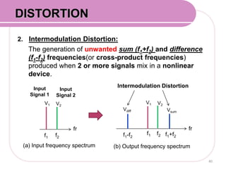
- 40. 2. Intermodulation Distortion:
The generation of unwanted sum (f1+f2) and difference
(f1-f2) frequencies(or cross-product frequencies)
produced when 2 or more signals mix in a nonlinear
device.
40
DISTORTION
V1
fr
f1
(a) Input frequency spectrum
Intermodulation Distortion
(b) Output frequency spectrum
Input
Signal 2
f2
V2
Input
Signal 1
V1
fr
f1 f2
V2
f1+f2f1-f2
Vdiff Vsum
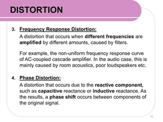
- 41. 3. Frequency Response Distortion:
A distortion that occurs when different frequencies are
amplified by different amounts, caused by filters.
For example, the non-uniform frequency response curve
of AC-coupled cascade amplifier. In the audio case, this is
mainly caused by room acoustics, poor loudspeakers etc.
4. Phase Distortion:
A distortion that occurs due to the reactive component,
such as capacitive reactance or inductive reactance. As
the results, a phase shift occurs between components of
the original signal.
41
DISTORTION
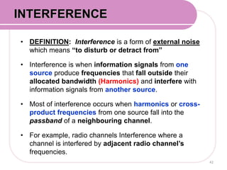
- 42. • DEFINITION: Interference is a form of external noise
which means “to disturb or detract from”
• Interference is when information signals from one
source produce frequencies that fall outside their
allocated bandwidth (Harmonics) and interfere with
information signals from another source.
• Most of interference occurs when harmonics or cross-
product frequencies from one source fall into the
passband of a neighbouring channel.
• For example, radio channels Interference where a
channel is interfered by adjacent radio channel’s
frequencies.
42
INTERFERENCE
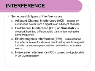
- 43. • Some possible types of interference are:
i. Adjacent-Channel Interference (ACI) - caused by
extraneous power from a signal in an adjacent channel.
ii. Co-Channel Interference (CCI) or Crosstalk - is
crosstalk from two different radio transmitters using the
same frequency.
iii. Electromagnetic Interference (EMI) - is disturbance
that affects an electrical circuit due to either electromagnetic
induction or electromagnetic radiation emitted from an external
source.
iv. Inter-carrier interference (ICI) - caused by doppler shift
in OFDM modulation
43
INTERFERENCE
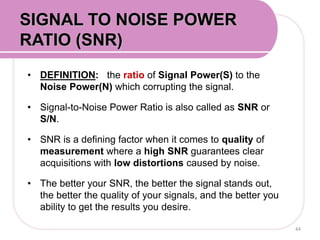
- 44. • DEFINITION: the ratio of Signal Power(S) to the
Noise Power(N) which corrupting the signal.
• Signal-to-Noise Power Ratio is also called as SNR or
S/N.
• SNR is a defining factor when it comes to quality of
measurement where a high SNR guarantees clear
acquisitions with low distortions caused by noise.
• The better your SNR, the better the signal stands out,
the better the quality of your signals, and the better you
ability to get the results you desire.
44
SIGNAL TO NOISE POWER
RATIO (SNR)
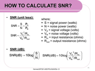
- 45. • SNR (unit less):
• SNR (dB):
45
N
S
10logSNR(dB)
where;
S = signal power (watts)
N = noise power (watts)
VS = signal voltage (volts)
VN = noise voltage (volts)
Rin = input resistance (ohms)
Rout = output resistance (ohms)
NP
PS
N
S
SNR
out
2
2
S
/RV
/RV
10logSNR(dB)
N
in
outN
in
/RV
/RV
SNR 2
2
S
HOW TO CALCULATE SNR?
Hanisah/EP301/JKE/POLISAS/Dis 12
- 46. For an amplifier with an output signal power of 10W and
an output noise power of 0.01W, determine the signal to
noise power ratio. [answ: 30dB]
Solution:
46
EXAMPLE 1:
- 47. For an amplifier with an output signal voltage of 4V, and
output noise voltage of 0.005V and an input and output
resistance of 50Ω, determine the signal-to-noise power
ratio. [answ: 58.06 dB]
Solution:
47
EXAMPLE 2:
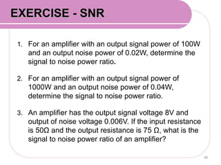
- 48. 1. For an amplifier with an output signal power of 100W
and an output noise power of 0.02W, determine the
signal to noise power ratio.
2. For an amplifier with an output signal power of
1000W and an output noise power of 0.04W,
determine the signal to noise power ratio.
3. An amplifier has the output signal voltage 8V and
output of noise voltage 0.006V. If the input resistance
is 50Ω and the output resistance is 75 Ω, what is the
signal to noise power ratio of an amplifier?
48
EXERCISE - SNR
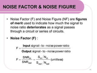
- 49. • Noise Factor (F) and Noise Figure (NF) are figures
of merit used to indicate how much the signal to
noise ratio deteriorates as a signal passes
through a circuit or series of circuits.
• Noise Factor (F) :
49
(unitless)
NS
NS
SNR
SNR
F
ratiopowernoise-to-signal
ratiopowernoise-to-signal
F
outout
inin
out
in
Output
Input
NOISE FACTOR & NOISE FIGURE
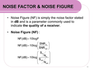
- 50. • Noise Figure (NF) is simply the noise factor stated
in dB and is a parameter commonly used to
indicate the quality of a receiver.
• Noise Figure (NF) :
50
NOISE FACTOR & NOISE FIGURE
out
out
in
in
out
in
N
S
N
S
10logNF(dB)
SNR
SNR
10logNF(dB)
10logFNF(dB)
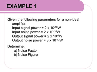
- 51. Given the following parameters for a non-ideal
amplifier;
Input signal power = 2 x 10⁻¹⁰W
Input noise power = 2 x 10-18W
Output signal power = 2 x 10⁻⁴W
Output noise power = 8 x 10-12W
Determine;
a) Noise Factor
b) Noise Figure
51
EXAMPLE 1
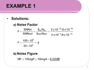
- 52. • Solutions:
a) Noise Factor
b) Noise Figure
52
EXAMPLE 1
4
1025
10100
F
10x/810x2
10x/210x2
/NS
/NS
SNRout
SNRin
F
6
6
12-4-
18-10-
outout
inin
6.02dB10log410logFNF
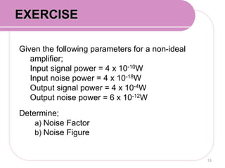
- 53. Given the following parameters for a non-ideal
amplifier;
Input signal power = 4 x 10⁻¹⁰W
Input noise power = 4 x 10-18W
Output signal power = 4 x 10⁻⁴W
Output noise power = 6 x 10-12W
Determine;
a) Noise Factor
b) Noise Figure
53
EXERCISE
- 54. Given the input signal to noise power ration of a non-
linear amplifier is 100,000 and its output signal to noise
power ratio is 25,000. Determine its Noise Figure.
[answ: 6.02 dB]
Solution:
54
EXAMPLE 2:
- 55. 1.5 Know the frequency spectrum, bandwidth, and
wavelength.
1.6 Apply bandwidth and wavelength formula.
At the end of this learning session, student should be able to
explain and apply :
- Frequency spectrum
- Bandwidth
- Wavelength
55
- 56. FREQUENCY SPECTRUM
56
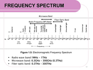
- 57. Figure 1.5: Electromagnetic Frequency Spectrum
Fiber Optic Band
Radio Frequency (RF) Band
Microwave Band
Radio wave band:1MHz - 1THz
Microwave band: 0.3GHz - 300GHz (0.3THz)
Fiber optic band: 0.3THz – 300THz
57
FREQUENCY SPECTRUM
- 58. 58
FREQUENCY SPECTRUM
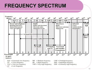
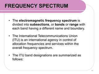
- 59. • The electromagnetic frequency spectrum is
divided into subsections, or bands or range with
each band having a different name and boundary.
• The International Telecommunications Union
(ITU) is an international agency in control of
allocation frequencies and services within the
overall frequency spectrum.
• The ITU band designations are summarized as
follows:
59
FREQUENCY SPECTRUM
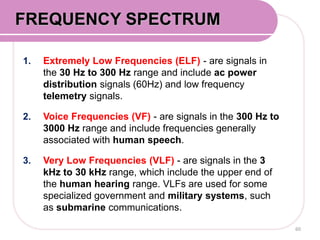
- 60. 1. Extremely Low Frequencies (ELF) - are signals in
the 30 Hz to 300 Hz range and include ac power
distribution signals (60Hz) and low frequency
telemetry signals.
2. Voice Frequencies (VF) - are signals in the 300 Hz to
3000 Hz range and include frequencies generally
associated with human speech.
3. Very Low Frequencies (VLF) - are signals in the 3
kHz to 30 kHz range, which include the upper end of
the human hearing range. VLFs are used for some
specialized government and military systems, such
as submarine communications.
60
FREQUENCY SPECTRUM
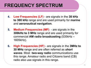
- 61. 4. Low Frequencies (LF) - are signals in the 30 kHz
to 300 kHz range and are used primarily for marine
and aeronautical navigation.
5. Medium Frequencies (MF) - are signals in the
300kHz to 3 MHz range and are used primarily for
commercial AM radio broadcasting (535kHz –
1605kHz).
6. High Frequencies (HF) - are signals in the 3MHz to
30 MHz range and are often referred as short
waves. Most two-way radio communications use
this range. Amateur radio and Citizens band (CB)
radio also use signals in this range.
61
FREQUENCY SPECTRUM
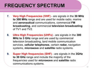
- 62. 7. Very High Frequencies (VHF) - are signals in the 30 MHz
to 300 MHz range and are used for mobile radio, marine
and aeronautical communications, commercial FM
broadcasting, and commercial television broadcasting
of TV1 and TV2.
8. Ultra High Frequencies (UHFs) - are signals in the 300
MHz to 3 GHz range and are used by commercial
television broadcasting, land mobile communication
services, cellular telephones, certain radar, navigation
systems, microwave and satellite radio systems.
9. Super High frequencies (SHF) - are signals in the 3GHz
to 30 GHz range and include the majority of the
frequencies used for microwave and satellite radio
communications systems.
62
FREQUENCY SPECTRUM
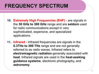
- 63. 10. Extremely High Frequencies (EHF) - are signals in
the 30 GHz to 300 GHz range and are seldom used
for radio communications except in very
sophisticated, expensive, and specialized
applications.
11. Infrared - Infrared frequencies are signals in the
0.3THz to 300 THz range and are not generally
referred to as radio waves. Infrared refers to
electromagnetic radiation generally associated with
heat. Infrared signals are used in the heat-seeking
guidance systems, electronic photography, and
astronomy.
63
FREQUENCY SPECTRUM
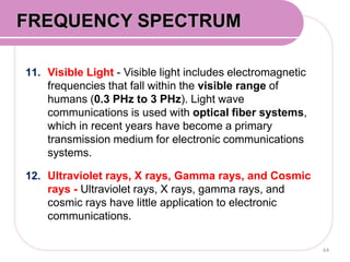
- 64. 11. Visible Light - Visible light includes electromagnetic
frequencies that fall within the visible range of
humans (0.3 PHz to 3 PHz). Light wave
communications is used with optical fiber systems,
which in recent years have become a primary
transmission medium for electronic communications
systems.
12. Ultraviolet rays, X rays, Gamma rays, and Cosmic
rays - Ultraviolet rays, X rays, gamma rays, and
cosmic rays have little application to electronic
communications.
64
FREQUENCY SPECTRUM
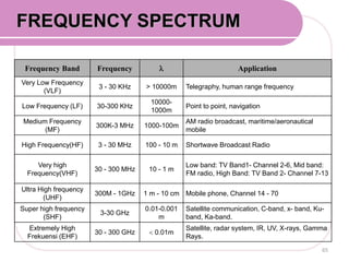
- 65. FREQUENCY SPECTRUM
65
Frequency Band Frequency Application
Very Low Frequency
(VLF)
3 - 30 KHz > 10000m Telegraphy, human range frequency
Low Frequency (LF) 30-300 KHz
10000-
1000m
Point to point, navigation
Medium Frequency
(MF)
300K-3 MHz 1000-100m
AM radio broadcast, maritime/aeronautical
mobile
High Frequency(HF) 3 - 30 MHz 100 - 10 m Shortwave Broadcast Radio
Very high
Frequency(VHF)
30 - 300 MHz 10 - 1 m
Low band: TV Band1- Channel 2-6, Mid band:
FM radio, High Band: TV Band 2- Channel 7-13
Ultra High frequency
(UHF)
300M - 1GHz 1 m - 10 cm Mobile phone, Channel 14 - 70
Super high frequency
(SHF)
3-30 GHz
0.01-0.001
m
Satellite communication, C-band, x- band, Ku-
band, Ka-band.
Extremely High
Frekuensi (EHF)
30 - 300 GHz 0.01m
Satellite, radar system, IR, UV, X-rays, Gamma
Rays.
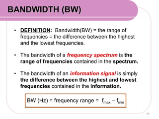
- 66. • DEFINITION: Bandwidth(BW) = the range of
frequencies = the difference between the highest
and the lowest frequencies.
• The bandwidth of a frequency spectrum is the
range of frequencies contained in the spectrum.
• The bandwidth of an information signal is simply
the difference between the highest and lowest
frequencies contained in the information.
66
BANDWIDTH (BW)
BW (Hz) = frequency range = fmax – fmin
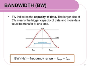
- 67. • BW indicates the capacity of data. The larger size of
BW means the bigger capacity of data and more data
could be transfer at one time.
67
BW (Hz) = frequency range = fmax – fmin
fmaxfmin
BANDWIDTH (BW)
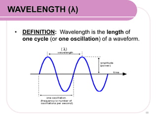
- 68. • DEFINITION: Wavelength is the length of
one cycle (or one oscillation) of a waveform.
68
WAVELENGTH (λ)
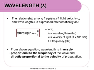
- 69. • The relationship among frequency f, light velocity c,
and wavelength λ is expressed mathematically as :
• From above equation, wavelength is inversely
proportional to the frequency of the wave and
directly proportional to the velocity of propagation.
69
WAVELENGTH (λ)
f
c
λwavelegth,
where;
λ = wavelength (meter)
c = velocity of light (3 x 10⁸ m/s)
f = frequency (Hz)
Hanisah/EP301/JKE/POLISAS/Dis 12
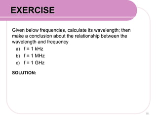
- 70. Given below frequencies, calculate its wavelength; then
make a conclusion about the relationship between the
wavelength and frequency
a) f = 1 kHz
b) f = 1 MHz
c) f = 1 GHz
SOLUTION:
70
EXERCISE
- 71. 1.7 Understand Transmission Modes
At the end of this learning session, student
should be able to explain :
- Transmission modes
71
- 72. Transmission mode
72
- 73. TRANSMISSION MODES
Transmission mode is the flow of information signal
between two points.
These modes direct the direction of flow of
information signal.
There are three modes of transmission for
communications circuit:
a. Simplex
b. Half duplex
c. Full duplex
Hanisah/ep301/jke/polisas/dis'11
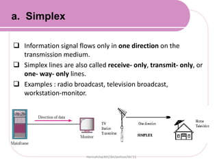
- 74. Information signal flows only in one direction on the
transmission medium.
Simplex lines are also called receive- only, transmit- only, or
one- way- only lines.
Examples : radio broadcast, television broadcast,
workstation-monitor.
Hanisah/ep301/jke/polisas/dis'11
a. Simplex
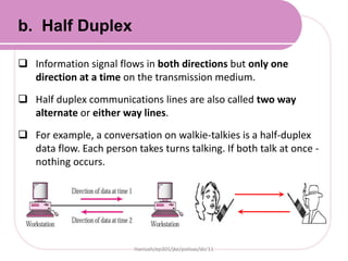
- 75. Information signal flows in both directions but only one
direction at a time on the transmission medium.
Half duplex communications lines are also called two way
alternate or either way lines.
For example, a conversation on walkie-talkies is a half-duplex
data flow. Each person takes turns talking. If both talk at once -
nothing occurs.
Hanisah/ep301/jke/polisas/dis'11
b. Half Duplex
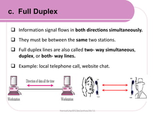
- 76. Information signal flows in both directions simultaneously.
They must be between the same two stations.
Full duplex lines are also called two- way simultaneous,
duplex, or both- way lines.
Example: local telephone call, website chat.
Hanisah/ep301/jke/polisas/dis'11
c. Full Duplex
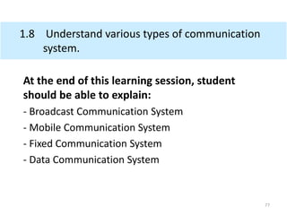
- 77. 1.8 Understand various types of communication
system.
At the end of this learning session, student
should be able to explain:
- Broadcast Communication System
- Mobile Communication System
- Fixed Communication System
- Data Communication System
77
- 78. TYPES of COMMUNICATION
SYSTEM
78
- 79. There are 4 types of Communication System;
i. Broadcast Communication System
ii. Mobile Communication System
iii. Fixed Communication System
iv. Data Communication System
79
TYPES of COMMUNICATION SYSTEM
- 80. • DEFINITION: A broadcast is the wireless transmission
of audio and video signal to a receiver via radio,
television, or others.
• It is a method of sending a signal where multiple
receivers may receive from a single sender.
• Broadcast is a type of communications called Simplex
(data flow in one direction).
• There is no interaction between the originator of the
content and the user of the content, so if the content
delivery is delayed by even a second or so, there will
be little effect on the value of the communications.
80
1. BROADCAST COMMUNICATION
- 81. Historically, there have been several different types of
electronic broadcasting media:
1. Telephone broadcasting (1881)
2. Radio broadcasting (1906)
3. Television broadcasting (telecast) (1925)
4. Cable radio (1928)
5. Satellite television (1974) and Satellite radio (1990)
6. Webcasting of video/television (1993) and
audio/radio (1994) streams.
81
1. BROADCAST COMMUNICATION
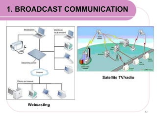
- 82. 82
1. BROADCAST COMMUNICATION
Satellite TV/radio
Webcasting
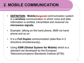
- 83. • DEFINITION: Mobile(bergerak) communication system
is a wireless communication in which voice and data
information is emitted, transmitted and received via
microwave signals.
• Example: talking on the hand phone, SMS via hand
phone and so on
• It is a Full Duplex communication (data flow in 2
directions simultaneously).
• Using GSM (Global System for Mobile) which is a
standard set developed by the European
Telecommunications Standards Institute (ETSI)
83
2. MOBILE COMMUNICATION
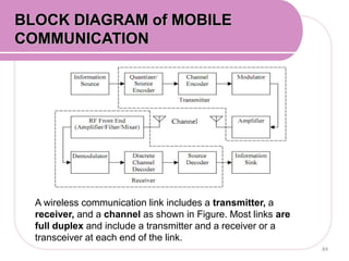
- 84. A wireless communication link includes a transmitter, a
receiver, and a channel as shown in Figure. Most links are
full duplex and include a transmitter and a receiver or a
transceiver at each end of the link.
BLOCK DIAGRAM of MOBILE
COMMUNICATION
84
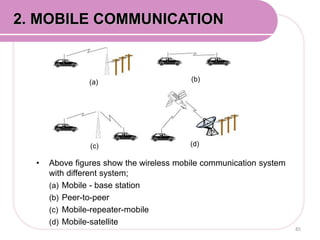
- 85. • Above figures show the wireless mobile communication system
with different system;
(a) Mobile - base station
(b) Peer-to-peer
(c) Mobile-repeater-mobile
(d) Mobile-satellite
85
2. MOBILE COMMUNICATION
(a) (b)
(c) (d)
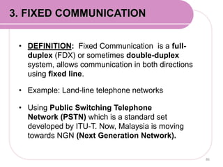
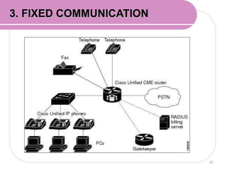
- 86. • DEFINITION: Fixed Communication is a full-
duplex (FDX) or sometimes double-duplex
system, allows communication in both directions
using fixed line.
• Example: Land-line telephone networks
• Using Public Switching Telephone
Network (PSTN) which is a standard set
developed by ITU-T. Now, Malaysia is moving
towards NGN (Next Generation Network).
86
3. FIXED COMMUNICATION
- 87. 3. FIXED COMMUNICATION
87
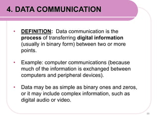
- 88. • DEFINITION: Data communication is the
process of transferring digital information
(usually in binary form) between two or more
points.
• Example: computer communications (because
much of the information is exchanged between
computers and peripheral devices).
• Data may be as simple as binary ones and zeros,
or it may include complex information, such as
digital audio or video.
88
4. DATA COMMUNICATION
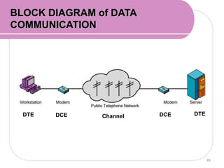
- 89. DTE DTEDCE DCEChannel
BLOCK DIAGRAM of DATA
COMMUNICATION
89
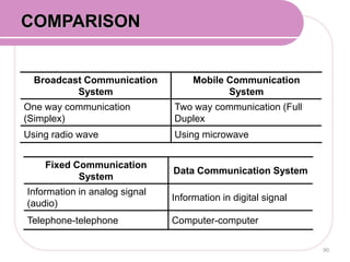
- 90. Broadcast Communication
System
Mobile Communication
System
One way communication
(Simplex)
Two way communication (Full
Duplex
Using radio wave Using microwave
Fixed Communication
System
Data Communication System
Information in analog signal
(audio)
Information in digital signal
Telephone-telephone Computer-computer
COMPARISON
90
- 91. REFERENCES
• Wayne T. (2004). Electronic Communication Systems:
Fundamentals Through Advance (6th ed.). Prentice
Hall. ISBN-10: 0130453501 or ISBN-13:
9780130453501
• Miller, Gary M. (2008). Modern Electronic
Communication (9th ed.). Prentice Hall. ISBN : 0-13-
225113-2.
• Mohd Azaini Maarof. Abdul Hanan Abdullah.
Komunikasi Data. Universiti Teknologi Malaysia. ISBN
983-52-0298-2.
![For an amplifier with an output signal power of 10W and
an output noise power of 0.01W, determine the signal to
noise power ratio. [answ: 30dB]
Solution:
46
EXAMPLE 1:](https://image.slidesharecdn.com/chapter1dep3273-150521043905-lva1-app6892/85/Chapter-1-dep3273-46-320.jpg)
![For an amplifier with an output signal voltage of 4V, and
output noise voltage of 0.005V and an input and output
resistance of 50Ω, determine the signal-to-noise power
ratio. [answ: 58.06 dB]
Solution:
47
EXAMPLE 2:](https://image.slidesharecdn.com/chapter1dep3273-150521043905-lva1-app6892/85/Chapter-1-dep3273-47-320.jpg)
![Given the input signal to noise power ration of a non-
linear amplifier is 100,000 and its output signal to noise
power ratio is 25,000. Determine its Noise Figure.
[answ: 6.02 dB]
Solution:
54
EXAMPLE 2:](https://image.slidesharecdn.com/chapter1dep3273-150521043905-lva1-app6892/85/Chapter-1-dep3273-54-320.jpg)