Download
1 / 75
810 likes | 1.22k Views
Structural Design. Introduction. It is necessary to evaluate the structural reliability of a proposed design to ensure that the product will perform adequately during assembly and service
 vanna
vanna

E N D
Structural Design
Introduction • It is necessary to evaluate the structural reliability of a proposed design to ensure that the product will perform adequately during assembly and service • The objective of the structural design process is to generate a part design that will withstand the loads or imposed deflections that will be encountered during service
Introduction • Since it is not always possible to quantify the loading conditions with certainty, a series of structural design calculations are performed • At anticipated loading during normal service conditions • Under conditions that represent the worst case scenario
Design Methodology • Design decisions can be made by using structural engineering relations that allow a designer to estimate the stresses or strains that occur when a product is subjected to a mechanical load or imposed deflection • Simplification are made regarding material properties, regularity of form and boundary conditions to obtain the estimate of how the part will perform
Design Methodology • Use classical formulas for stress and strain • Assume isotropic, homogeneous, elastic behavior • Compare calculated stresses and strains with the plastics limits • Can use finite element analysis program • Accuracy of results depends on the ability of the designer to quantify the problem correctly
Quantifying the Design Problem • The designer needs to assess and specify a number of factors before beginning the structural calculations • Part geometry • Type of support • Loading conditions • Environmental conditions • Mechanical properties • Safety factors
Quantifying the Design Problem • Once these item have been quantified, the designer • Performs a series of design calculations • Examines the results • Alters the design if needed • Recalculate • Iterate until the desired results are obtained
Simplifying Part Geometry • Classical formulas for stress and strain have been developed for most regular geometries • Straight, tapered or curved beams • Columns • Plates • Shells • Common practice to divide parts with a complex geometries into a series of subparts having regular geometries and evaluating the stresses and strains in each subpart
Stress Concentrations • Stress distribution in parts are influenced by the presence of features such as corners, holes or any discontinuity in the design geometry • Stresses concentrate at the these discontinuities, leading to local stress values that are significantly higher than those in areas nearby
Stress Concentration Problem • The yield stress for a polymer is 100,000 psi. What is the allowable design stress for the polymer in the following application?
Stress Concentration Problem
Stress Concentration Chart
Types of Support • In order for loaded parts to remain in equilibrium, the balancing forces are the reaction forces at the supports • Most real life products have support geometries which differ from the idealized case • Designer must select the conservative case
Types of Support • Guided is support at the end of the beams that prevent rotation, but permits longitudinal and transverse displacement • Free or unsupported is when the beam is totally free to rotate in any direction • Held is support at the end of the beam that prevents longitudinal and transverse displacement but permits rotation
Types of Support • Simply Supported is support at the end of the beam that prevents transverse displacement, but permits rotation and longitudinal displacement • Fixed is support at the ends of the beam that prevents rotation and transverse displacement, but permits longitudinal displacement
Idealized Supports
Idealized Supports
Loading Conditions • Once the part geometry and support conditions have been established, the loads acting on the product must be defined and quantified into a form that is suitable for a stress calculation • Must quantify the magnitude, direction and type of load • Load type can be concentrated at a point, line or boundary, or distributed over an area
Concentrated and Distributed Loads
Multiple Static Loads • When a series of loads are acting on a product, the total stress or deflection can be found by superposition • Since stress and deflection are linear in relation to load, the loads can be added together to get the total load
Plastic Material Properties • The stress strain behavior of the plastic must also be quantified • The maximum stress or strain estimates that are calculated from loading must be compared to the materials stress strain behavior to determine if these values are within acceptable limits
Safety Factors • There are a large number of uncertainties associated with plastic part design and the manufacturing process • The permissible design stress level can be determined by combining the material percentage utilization factor, ST, the yield stress and the stress concentration factor, K • Design stress < (ST * Yield stress)/K
Safety Factors • ST=S1*S2*S3*S4 • S1 is risk of injury to people in event of failure • 1.0 if no risk of injury • 0.7 is possible injury • 0.5 if probable injury • S2 is the processing factor • 1.0 for neat polymer • 0.8 for fiber orientated in the direction of maximum stress • 0.5 for fiber oriented perpendicular to the direction of maximum stress
Safety Factors • S3 is the stress calculation accuracy • 1.0 for finite element analysis • 0.75 for classical formula • 0.5 for estimates • S4 is material degradation • <1.0 values are material specific
Beams • A structural member designed to support loads at various points along the member • Generally long, straight bars with a cross section designed to provide the most effective resistance to shear and bending • The classical formulas used to calculate stress and deflection are based on assumption that are not realistic for plastics • However the formulas are useful to provide an estimate
Beams
Beams • The behavior of a beam under load is most easily described using an example when the beam is horizontal and the load and reaction are vertical • Once loaded the beam will deflect • Material on the concave side will shorten • It is in compression • Material on the convex side will lengthen • It is in tension
Beams • The neutral surface of the beam • Is the plane where stress and strain are zero • Is normal to the plane of the load and is also the horizontal centroid axis • Fiber stresses and strains are proportional to the distance from the neutral surface
Beams • Fiber stress at any point P, within the boundary of the beam is • The maximum stress occurs at the points furthest from the neutral surface on the outer surface • M is the bending moment, I is the moment of inertia, y is the distance from the neutral surface to p and c is the distance from the neutral surface to the outer surface
Plane Areas • Plane areas are cross sections of beams • In order to design a beam with effective cross section for a loading application, the area properties of a beam cross section must be determined • The area properties include • The centroid axis • The bending moment • The moment of inertia • The section modulus
Plane Areas
Centroid Axis • Centroid is the point in the plane of an area about any axis the which the moment of the area is zero • Coincides with the center of gravity • The centroid axis of an area is an axis that passes through the centroid
Statical moment • First moment of the area • It’s the sum of the products obtained by multiplying each element of area, dA, by the first power of its distance from the centroid axis
Moment of Inertia • Second moment of area • Determines the ability of a beam to support a load • Moment of inertia is equal to the sum of the products obtained by multiplying each element of area, dA, by the square of the distance for the centroid axis
Parallel Axis Theorem • Used to determine moment of inertia values for complicated geometries by finding the moment of inertia about any axis • Where IT is the total moments of inertia about any axis, Ic is the moments of inertia with respect to the centroid parallel axis and yi is the distance between the parallel axis and Ai is the cross sectional area
Section Modulus • The section modulus(Z) for a symmetrical cross section is defined as the second moment of area(I) divided by the distance from the axis to the most remote point of that section area(c)
Area Properties • Area properties for more complex geometries are given in handbook and can be calculated by breaking down the complex geometry into regular shapes to produce a composite area • The moment of inertia of a composite area is equal to the sum of the individual moment of inertias
Area Properties • A void in the cross section can be taken into account by subtracting the moment of inertia for the void area • The statical moment of a composite area is equal to the sum of the individual statical moments
Area Properties • The total area of the composite area is the sum of the individual areas • The distance between the reference axis and the centroid axis of the composite area is
Area Properties • The moment of inertia for the entire composite section about the composite sections centroid axis is • Where IT is the total moments of inertia, Ic is the moments of inertia with respect to the centroid axis of each section and yi is the distance between the sections centroid axis and the composites centroid axis and Ai is the sections cross sectional area
Deflection • The formula to use depends on the support condition and the type of load • See Formulas for Bending Moments • Deflection formula for a simply supported beam subjected to a partially distributed load • y is the deflection, w is the load, L in the unsupported length, E is the modulus and I is the moment of inertia
Structural Design Samples • Rectangle • I-beam
Rectangle .125” 6.0”
I-Beam Fig 4.26 p218 malloy
I-Beam
I-Beam
I-Beam
I-Beam • Solid minus two voids • Centroid axis for each of the rectangles are the same as the centroid axis of the entire composite beam
I-Beam
I-Beam • Three solid sections • The centroid axes for the outer sections not the same as the inner section or as the composite beam • Need to use the parallel axis theorm

Structural Steel Design. T. Michael Toole, Ph.D., P.E. Daniel Treppel Stephen Van Nosdall Bucknell University. Learning Objectives . Summarize the Prevention through Design Concept List reasons why project owners may wish to have PtD performed on their projects
1.3k views • 80 slides
Bridges. TED 316 – Structural Design. A bridge is a structure built to span physical obstacles such as a body of water, valley, or road, for the purpose of providing passage over the obstacle. (Wikipedia). Bridges . Nature of the terrain where the bridge is constructed Length of span
321 views • 18 slides
Design of Steel Structural . 803459-3. Mohammed Alsabban. masabban@uqu.edu.sa Office : 1153 Ext. 1142 Mobile 0-5555-10-233 Office Hours: Sun 8am:10am Tue 11am:12 noon Wed 5pm:6pm. Text. Book: Structural Steel Design Authors: Jack C. McCormac and Stephen F. Csernak
1.06k views • 36 slides
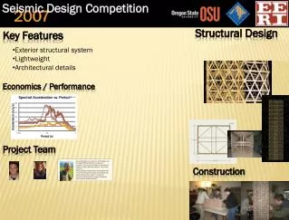
Seismic Design Competition. 2007 . Structural Design. Key Features. Exterior structural system Lightweight Architectural details. Economics / Performance. Project Team.
410 views • 1 slides
Photo courtesy of Thinkstock. Structural Steel Design. EDUCATION MODULE. Developed by T. Michael Toole, Ph.D., PE Daniel Treppel Stephen Van Nosdall Bucknell University. Guide for Instructors. Learning Objectives . Explain the Prevention through Design (PtD) concept.
1.29k views • 91 slides
Building Classifications: Construction Types. TED 316 – Structural Design. Based on how the building is constructed. Relates to: Materials used Combustibility Fire-resistance. Construction types defined. Types IA and IB Types IIA and IIB Types IIIA and IIIB Type IV Types VA and VB.
262 views • 10 slides
Construction Materials Concrete & Masonry. TED 316 – Structural Design. Been used since the Roman Empire Key event in the history of architecture Termed the Roman Architectural Revolution Similar to modern concrete and nearly as strong
215 views • 11 slides
CIVIL/STRUCTURAL DESIGN. http://www.veoliaenvironmentalservices.com/images/veolia_proprete_stockage%20dechets_us_ra_p43.jpg. CIVIL COMPONENTS . DRAINAGE UNDERGROUND SUPPORT OVERALL GEOTECHNICAL VEHICULAR TRANSPORT. http://www.duluthstreams.org/stormwater/toolkit/images/ugStorTyp.gif.
300 views • 12 slides
Building Classifications: Occupancies. TED 316 – Structural Design. Most things have classifications Objective classifications Drivers’ licenses Hazardous materials Tests and assignments (hopefully) Subjective classifications Social status Favorite movies. types of classifications.
262 views • 12 slides
Structural Design Considerations. Small or 0° turn radius Given size restriction and ground clearance Friction Type of drive-train Weight and center of gravity location. Wheels . First considered to determine range of chassis size to work with
225 views • 7 slides
Structural Design. 16.3.07 pm (Building Structure Design a) 30.3.07 pm (Building Structure Design b) 13.4.07 pm (Foundation Structure Design) 20.4.07 pm (Bridge Structure Design)
198 views • 1 slides
Virtual Wallet Structural Design. Gates Winkler Jordan Samuel Fei Yin Shen October 5, 2009. To create a handheld device which will save money and time through budget assistance and improve the shopping experience. Status. Finished Flow Chart Behavioral Verilog Transistor Estimate
208 views • 10 slides
Structural Designing is essentially subject of civil engineering and it's really high on structural engineering. Structural Designing, the term itself claim that whenever we are accomplishing the building for any constructing. To prepare our students for a fulfilling professional career.We are committed to upholding our values of providing excellence in training.
340 views • 8 slides
Design of Structural Elements. Composite panel design. Laminate analysis gives the fundamental information on stiffness, elastic constants and uniaxial strengths. For structural analysis, we need in-plane stiffness [A] and flexural rigidity [D]. A 11. D 66. D 22. D 12. A 12. D 11. A 22.
730 views • 38 slides
Structural Steel Design. T. Michael Toole, Ph.D., P.E. Daniel Treppel Stephen Van Nosdall Bucknell University. Learning Objectives. Summarize the Prevention through Design Concept List reasons why project owners may wish to have PtD performed on their projects
1.08k views • 80 slides

CIVIL/STRUCTURAL DESIGN. http://www.veoliaenvironmentalservices.com/images/veolia_proprete_stockage%20dechets_us_ra_p43.jpg. CIVIL COMPONENTS. DRAINAGE UNDERGROUND SUPPORT OVERALL GEOTECHNICAL VEHICULAR TRANSPORT. http://www.duluthstreams.org/stormwater/toolkit/images/ugStorTyp.gif.
226 views • 12 slides
Design Pattern – Bridge (Structural). References Yih-shoung Chen, Department of Information Engineering, Feng Chia University,Taiwan, R.O.C. The Bridge Pattern, SENG 609.04 Design Patterns, University of Calgary The Bridge Pattern , CpSc 872 Software Engineering
276 views • 11 slides
PSE Structural engineers Melbourne has a large list of happy and satisfied clients, who appreciate their work quality and professionalism. Our services are very economical and surely gives you value for money. To ensure the usage of best quality material and steel-element, is their job. for more details : http://www.pseconsult.com.au/structural
96 views • 6 slides

Structural Inspection, Report, Engineering Inspection Services, Consultants & Solutions in Sydney, Australia ? Certified Engineer Experts | dorna.com.au.tttt tttt tttt tttt
122 views • 10 slides

Our Structural design engineers provide design services which includes Structural Drawing, Structural Design, Structural analysis and Rebar Schedule. We also offer Structural Design Consultancy and Structural Engineering Services in Qatar.
62 views • 5 slides
玻璃钢生产厂家高质量的玻璃钢雕塑设计广州玻璃钢人物雕塑制作玻璃钢人物卡通雕塑淄博玻璃钢雕塑厂时尚玻璃钢雕塑沧州肇庆玻璃钢卡通雕塑曲阳红日玻璃钢雕塑山南玻璃钢花盆甘肃楼盘玻璃钢动物雕塑小品制作商场创意商业美陈定制嘉兴玻璃钢仿铜雕塑定做价格成品玻璃钢花盆销售公司衢州玻璃钢陶瓷雕塑方案运城校园玻璃钢雕塑铜陵frp玻璃钢雕塑锻铜校园玻璃钢雕塑定做厂家芜湖玻璃钢动物雕塑设计北京通州玻璃钢花盆厂家frp玻璃钢雕塑厂商老鹰玻璃钢雕塑辽宁玻璃钢艺术雕塑宿迁玻璃钢广场雕塑浙江特色商场美陈有哪些佛山玻璃钢书本造型雕塑南宁佛像玻璃钢雕塑销售电话浙江玻璃钢雕塑摆件采购玻璃钢动物雕塑河北商场美陈批发价高质量玻璃钢雕塑定做价格鹤壁玻璃钢雕塑雕刻厂家电话香港通过《维护国家安全条例》两大学生合买彩票中奖一人不认账让美丽中国“从细节出发”19岁小伙救下5人后溺亡 多方发声单亲妈妈陷入热恋 14岁儿子报警汪小菲曝离婚始末遭遇山火的松茸之乡雅江山火三名扑火人员牺牲系谣言何赛飞追着代拍打萧美琴窜访捷克 外交部回应卫健委通报少年有偿捐血浆16次猝死手机成瘾是影响睡眠质量重要因素高校汽车撞人致3死16伤 司机系学生315晚会后胖东来又人满为患了小米汽车超级工厂正式揭幕中国拥有亿元资产的家庭达13.3万户周杰伦一审败诉网易男孩8年未见母亲被告知被遗忘许家印被限制高消费饲养员用铁锨驱打大熊猫被辞退男子被猫抓伤后确诊“猫抓病”特朗普无法缴纳4.54亿美元罚金倪萍分享减重40斤方法联合利华开始重组张家界的山上“长”满了韩国人?张立群任西安交通大学校长杨倩无缘巴黎奥运“重生之我在北大当嫡校长”黑马情侣提车了专访95后高颜值猪保姆考生莫言也上北大硕士复试名单了网友洛杉矶偶遇贾玲专家建议不必谈骨泥色变沉迷短剧的人就像掉进了杀猪盘奥巴马现身唐宁街 黑色着装引猜测七年后宇文玥被薅头发捞上岸事业单位女子向同事水杯投不明物质凯特王妃现身!外出购物视频曝光河南驻马店通报西平中学跳楼事件王树国卸任西安交大校长 师生送别恒大被罚41.75亿到底怎么缴男子被流浪猫绊倒 投喂者赔24万房客欠租失踪 房东直发愁西双版纳热带植物园回应蜉蝣大爆发钱人豪晒法院裁定实锤抄袭外国人感慨凌晨的中国很安全胖东来员工每周单休无小长假白宫:哈马斯三号人物被杀测试车高速逃费 小米:已补缴老人退休金被冒领16年 金额超20万